in this post we will learn how to make Automatic Railway Gate Control System Using AVR ATmega8
Here I am sharing automatic Railway Gate control system using AVR microcontroller Gates will close automatically when train arrival and open when train departure from crossing. The main purpose of this project is to avoid accidents and save time.
Sensor Setup - 1
Sensor Setup - 2
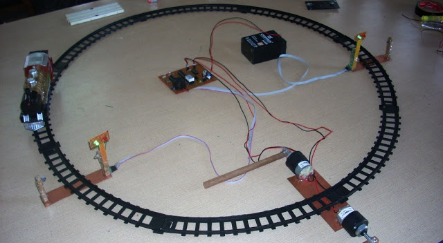
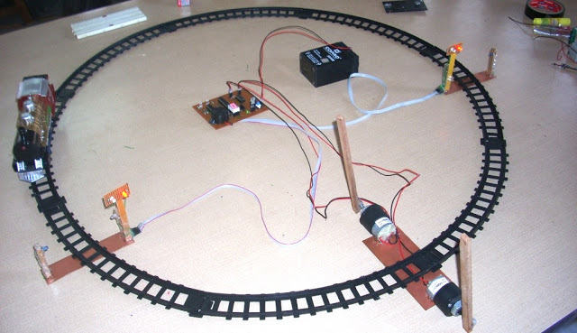
Step:4 Whole setup -
NOTE:-After making this project I realize some limitation, first it required different type of IR sensors which should not detect human interrupt and second thing is at gate closing time if any vehicle present in between and below the gate then gate should detect the presence of any vehicle or obstacle. If you resolve these then please share.
1>complete code + hex file
Here I am sharing automatic Railway Gate control system using AVR microcontroller Gates will close automatically when train arrival and open when train departure from crossing. The main purpose of this project is to avoid accidents and save time.
This project utilizes Two IR Tx./Rx. Pair is placed at either
side of the gate with some distance as shown in the pic above. When train cuts first sensor light
signal toggled from Green to Red; a buzzer gets activated for 2 seconds and
railway gate will closed. When train cuts second sensor then a countdown timer
starts and when it counts zero light signal again toggled from Red to Green ;
again buzzer gets activated for 2 Seconds and gates will closed. Timing for
countdown timer is set in the controller according to the speed and length of
the train. You can easily measure this timing for your toy train. I made this
bidirectional so train’s direction doesn’t matter.
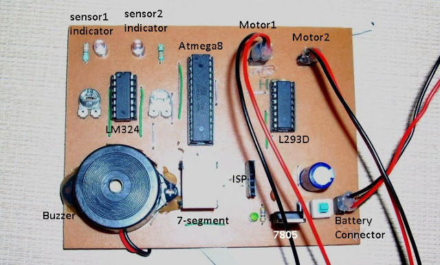
I design circuit using AVR ATmega8 microcontroller.IR sensors output is
connected to comparator LM324.LM324 generates TTL High/Low signal at its
output pins which is fed to MCU's pins as Input. According to input
from LM324 Micro-controller take action. Two DC Motors is used for
controlling the gate, these motor's current requirement is much more
then MCU hence we need a Motor Driver IC L293D.
Required Components:
1.DC Geared Motors RPM:30 - 2
2.IR Tx./Rx. Pairs - 2
3.MCU ATmega8 - 1
4.IC-LM324 - 1
5.IC-L293D - 1
6. Registers 470E - 10,10K-2,4.7K-1
7.Capacitors : 1000uF.16volt -1 , 100nF-1
8.Seven Segment CC - 1
9.Some LED's : 2- Green, 2-Red, 3 others
10.7805 -1
11.6Volt,4.5MAh Battery
12.some wires, burg strips etc.
and a Toy Train --
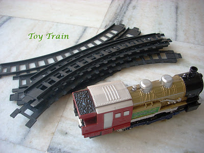 |
| Automatic Railway Gate Control System Using AVR ATmega8 with complete project report, code and circuit diagram. |
Making:
step 1 : First make the sensor setup.IR Tx./Rx. should be
connected in line of sight. Two signal LEDs. Total five wire comes out
from this sensor setup- VCC, GND, Sensor Output, Red LED anode, Green
LED anode. Distance between IR Tx./Rx. is about 12cm.
 | |
| Automatic Railway Gate Control System Using AVR ATmega8 with complete project report, code and circuit diagram. |
Sensor Setup - 2
 |
| Automatic Railway Gate Control System Using AVR ATmega8 with complete project report, code and circuit diagram. |
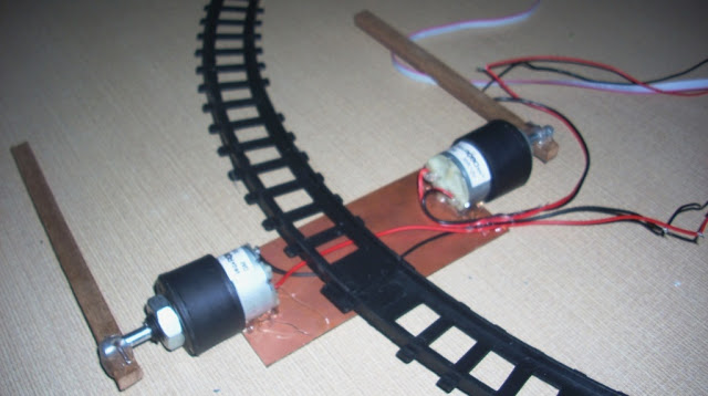
Step:2 Gear Motor's setup.
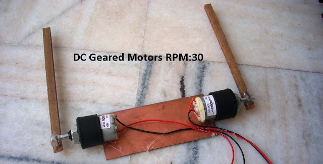 |
| Automatic Railway Gate Control System Using AVR ATmega8 with complete project report, code and circuit diagram. |
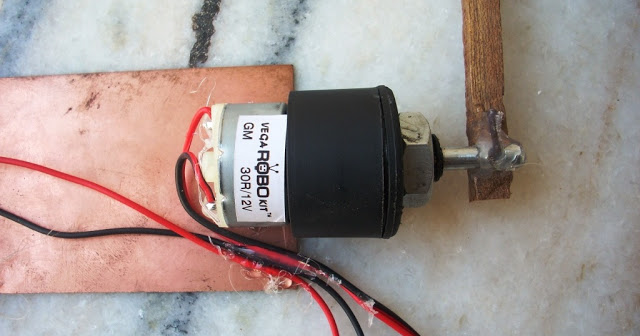 |
| Automatic Railway Gate Control System Using AVR ATmega8 with complete project report, code and circuit diagram. |
 |
| Automatic Railway Gate Control System Using AVR ATmega8 with complete project report, code and circuit diagram. |
 |
| Automatic Railway Gate Control System Using AVR ATmega8 with complete project report, code and circuit diagram. |
 |
| Automatic Railway Gate Control System Using AVR ATmega8 with complete project report, code and circuit diagram. |
 |
| Automatic Railway Gate Control System Using AVR ATmega8 with complete project report, code and circuit diagram. |
 |
| Automatic Railway Gate Control System Using AVR ATmega8 with complete project report, code and circuit diagram. |
NOTE:-After making this project I realize some limitation, first it required different type of IR sensors which should not detect human interrupt and second thing is at gate closing time if any vehicle present in between and below the gate then gate should detect the presence of any vehicle or obstacle. If you resolve these then please share.
1>complete code + hex file
download from here
2>
circuit diagram
download from here
No comments:
Post a Comment