Design circuit diagram in Proteus as bellow :-
+and+Proteus+(GSM+based+security+system+using+microcontroller+8051).jpg)
1> Microcontroller based control system with regulated power supply.
2> GSM Modem or phone.
3> Digital and Analog sensors and controlled devices.
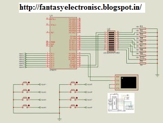
this figure is the circuit diagram of home/office security system. We can see that system has 10 LED's attached to microcontroller(89c51). These LED's can serve 2 jobs.
we can attach any external device with these signals like bulb or camera, or any suitable device using proper optocoupler and relays.
1st LED is flashing led, which is an indication that the system is running smoothly or not. 2nd LED is for alarm for security problems and remaining8 LED's can be used for controlling cameras in each of the room to take snaps of the person who has un-authorised access to that room.
Thus this is GPS based camera controlled security system for home/offices.
#include
#include
void initialize_GSM_modem(void);
void initialize_serialcommunication(void);
unsigned int counterup = 0;
unsigned char Command_CMGF[]="AT+CMGF=1\r";
// AT+CMGF for selecting Text Mode
unsigned char CtrlZ=0x1A;
// CTRL+Z for sedning SMS after the message has been entered
unsigned char Command_CMGS[]="AT+CMGS =+9233385xxxxx\r";
// recepient mobile number
unsigned char Command_AT[]="AT\r";
unsigned char msg02[]="Hello!";
// inputs
// if any of the push button is pressed logic zero will be detected by microcontroller on respective input pin
sbit input_door_1 = P1^0;
sbit input_door_2 = P1^1;
sbit input_door_3 = P1^2;
sbit input_door_4 = P1^3;
sbit input_door_5 = P1^4;
sbit input_door_6 = P1^5;
sbit input_door_7 = P1^6;
sbit input_door_8 = P1^7;
// coresponding output will be generated by applying logic one on respective output pin
sbit output_door_1 = P2^0;
sbit output_door_2 = P2^1;
sbit output_door_3 = P2^2;
sbit output_door_4 = P2^3;
sbit output_door_5 = P2^4;
sbit output_door_6 = P2^5;
sbit output_door_7 = P2^6;
sbit output_door_8 = P2^7;
sbit flashing = P3^6;
sbit alarm = P3^7;
void delay2(void)
unsigned int i;
for(i=0;i<25000;i++);
void main (void)
{
P1 =0xff; P2 = 0; alarm = 0; flashing = 0;
initialize_serialcommunication();
initialize_GSM_modem();
while (1)
{
flashing =~ flashing; delay2();
if(input_door_8 == 0){ output_door_8=0; alarm = 1;
puts("door # 1 is opened"); delay2(); while(!TI); TI = 0;SBUF = 0x1A;}
if(input_door_7 == 0){ output_door_7=0; alarm = 1;
puts("door # 2 is opened"); delay2(); while(!TI); TI = 0;SBUF = 0x1A;}
if(input_door_6 == 0){ output_door_6=0; alarm = 1;
puts("door # 3 is opened"); delay2(); while(!TI); TI = 0;SBUF = 0x1A;}
if(input_door_5 == 0){ output_door_5=0; alarm = 1;
puts("door # 4 is opened"); delay2(); while(!TI); TI = 0;SBUF = 0x1A;}
if(input_door_4 == 0){ output_door_4=0; alarm = 1;
puts("door # 5 is opened"); delay2(); while(!TI); TI = 0;SBUF = 0x1A;}
if(input_door_3 == 0){ output_door_3=0; alarm = 1;
puts("door # 6 is opened"); delay2(); while(!TI); TI = 0;SBUF = 0x1A;}
if(input_door_2 == 0){ output_door_2=0; alarm = 1;
puts("door # 7 is opened"); delay2(); while(!TI); TI = 0;SBUF = 0x1A;}
if(input_door_1 == 0){ output_door_1=0; alarm = 1;
puts("door # 8 is opened"); delay2(); while(!TI); TI = 0;SBUF = 0x1A;}
if(alarm == 1)
{
counterup++;
if(counterup>=10)
{
counterup = 0; alarm = 0; P2=0;}
}
}
}
void initialize_GSM_modem(void){
delay2();
puts(Command_AT);
delay2();
puts(Command_CMGF);
delay2();
puts(Command_CMGS);
delay2();
puts(msg02);
delay2();
while(!TI); TI = 0;
}
void initialize_serialcommunication(void)
TMOD = 0x20;
SCON = 0x50;
TH1 = 0xFD;
TL1 = 0xFD;
TR1 = 1;
TI = 1;
}
No comments:
Post a Comment